SPI connector v1
Ready products use the SPI bus for communication between chips on same PCB, it is wired case by case. Anyhow, while prototyping it is convinient to have a specified pinout: Connector for test PCBs and specific pin order for breadboard. This allows switching SPI device - microcontroller setups quickly.
SPI interface uses 2x5 FC-10P 2.54mm dual row IDC sockets connectors.
Connectors soldered to both microcontroller and device PCB boards are male. Ends of connecting cable are female. Flat ribbon cable can be used, and connect pin 1 to pin 1, pin 2 to pin 2… This spec supports connecting up to three slave devices to one master.
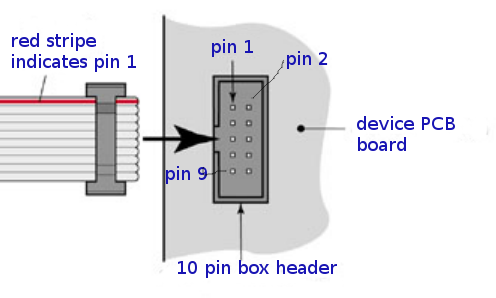
SPI connector and cable orientation - both controller board and device end the same pinout.
pin nr |
pin name |
description |
|---|---|---|
1 |
GND |
Ground. |
2 |
3.3V |
SPI operating voltage, typically 3.3V. Controller board powers the device. |
3 |
5V |
Controller board powers the device. This voltage is not yet decided. |
4 |
SCLK |
SPI clock from controller (master) to device (slave). |
5 |
MOSI |
Data from controller to device, master out/slave in. |
6 |
MISO |
Data from device to controller, master in/slave out. |
7 |
SS_1 |
Chip select, activates first SPI device. This signal is inverted, the device is activated when this is 0V and deactivated when 3.3V. |
8 |
SS_2 |
Chip select, activates second SPI device. This signal is inverted, the device is activated when this is 0V and deactivated when 3.3V. |
9 |
SS_3, GPIO A |
Either chip select, activates third SPI device. Or application specific GPIO pin A. (optional) |
10 |
GPIO B |
Application specific GPIO pin B. Specific use like display backlight control, etc. (optional) |
Connect SPI IDC to breadboard: Two separate “straight 1 x 5 pin strips” (pin numbers 1 - 5 and 6- 10) or one “breadboard friendly ribbon crimp connector” can be presssed into breadboard. Pin use as described in “connector pinout” above.
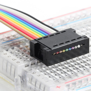
Ready breadboard friendly ribbon crimp connector 2x5.
PCB modules which can be pressed into breadboard should pin out same as ready breadboard ready crimp connector. The top row should contain pins 6 to 10 and the bottom row pins 1 to 5 as in connector pinout (VERIFY TOP/BOTTOM ROW ORDER).
31.7.2021/pekka